1. ปัญหา
เนื่องจากก่อนหน้านี้ ทางทีมได้พยายามเก็บข้อมูลแผนที่และระบุตำแหน่งหุ่นยนต์โดยใช้ LiDAR ร่วมกับ ROS (Robot Operating System) และ SLAM (Simultaneous Localization and Mapping) แต่พบปัญหาความไม่เสถียรในขั้นตอนการสร้างแผนที่ (Map) เพื่อระบุตำแหน่งของหุ่นยนต์เทียบกับแกนอ้างอิงของแผนที่ ทำให้ข้อมูลที่ได้มีความคลาดเคลื่อนสูงและตำแหน่งไม่นิ่ง
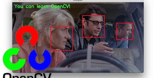
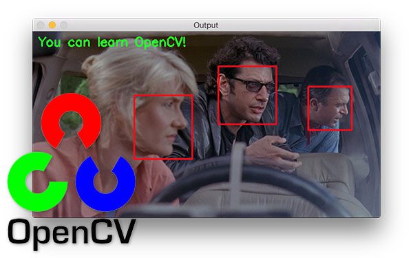
เพื่อแก้ไขปัญหาดังกล่าว จึงได้เสนอแนวคิดใหม่โดยเปลี่ยนมาใช้วิธีการทาง Image Processing เพื่อลดความซับซ้อนและข้อผิดพลาดในการทำงาน โดยหันมาใช้ OpenCV (Open Source Computer Vision Library) ซึ่งเป็นไลบรารีโอเพนซอร์สสำหรับงานประมวลผลภาพโดยเฉพาะ ร่วมกับ ArUco markers ซึ่งเป็นมาร์กเกอร์สี่เหลี่ยมที่ถูกออกแบบมาให้กล้องสามารถตรวจจับ ID และคำนวณตำแหน่งและทิศทาง (3D Pose) ได้อย่างรวดเร็วและแม่นยำ
แนวคิดนี้มีจุดประสงค์เพื่อสร้างแผนที่เสมือน (virtual map) จากมาร์กเกอร์ และใช้ในการติดตามว่าหุ่นยนต์อยู่ในตำแหน่งใดของแผนที่ รวมถึงทราบทิศทางว่าหุ่นยนต์กำลังหันหน้าไปในทิศทางใด
2. หลักการทำงานของโค้ด
แนวคิดของโค้ดนี้อธิบายแบบง่ายๆ คือการสร้าง “แผนที่เสมือน” (Virtual Map) โดยใช้ ArUco markers เป็นจุดอ้างอิงหลัก มีขั้นตอนดังนี้:
- การตั้งค่า (Setup):
- เราใช้ ArUco marker เพียงชุดเดียว (ในโค้ดคือ
DICT_4X4_50) ซึ่งเป็นชุด marker มาตรฐานที่ OpenCV รู้จัก
- เราใช้ ArUco marker เพียงชุดเดียว (ในโค้ดคือ
- ตัวหลัก (Key Markers):
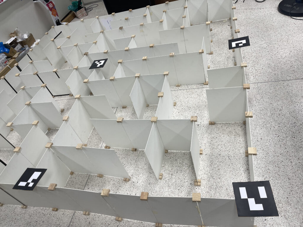
- ID 0 และ ID 1 (เสาหลักของแผนที่): Marker สองตัวนี้ทำหน้าที่เป็น “เสาหลัก” หรือ “หมุด” อ้างอิงสองมุมของสนาม โค้ดจะใช้ตำแหน่ง 3 มิติของ marker สองตัวนี้เป็นจุดเริ่มต้นและจุดสิ้นสุดในการ “ขึง” แผนที่เสมือน
- ID 10 (ตัวหุ่นยนต์): Marker นี้จะถูกติดตั้งไว้บนตัวหุ่นยนต์ เพื่อใช้เป็นตัวแทนตำแหน่งของหุ่นยนต์
- ขั้นตอนการทำงาน (Workflow):
- Step 1: ค้นหา Markers: เมื่อเปิดกล้อง, โค้ดจะสแกนภาพตลอดเวลาเพื่อค้นหา ArUco markers ที่อยู่ในชุด
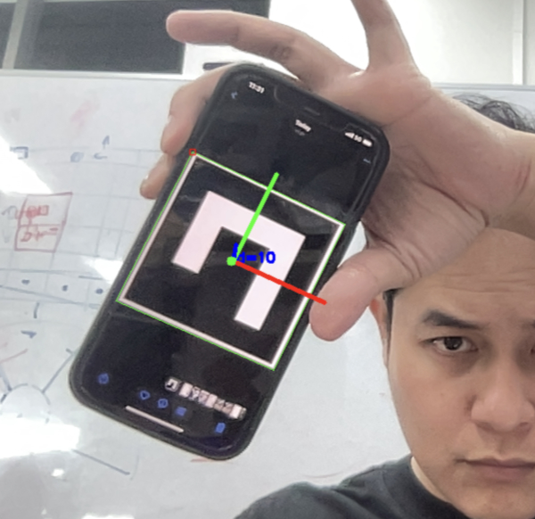
DICT_4X4_50 - Step 2: คำนวณตำแหน่ง 3D (Pose): เมื่อใดก็ตามที่เจอ marker (ไม่ว่าจะเป็น ID 0, 1, หรือ 10), โค้ดจะใช้ฟังก์ชันของ OpenCV เพื่อคำนวณตำแหน่งในโลก 3 มิติ (tvecs: x, y, z) และทิศทางการหัน (rvecs) ของ marker นั้นๆ เทียบกับกล้อง
- Step 3: สร้างแผนที่เสมือน (Map Generation): ถ้าโค้ดเจอ ID 0 และ ID 1 พร้อมกัน, มันจะใช้ตำแหน่ง 3D ของ marker สองตัวนี้เป็นจุดอ้างอิงในการคำนวณและวาด “แผนที่เสมือน” (Grid) ขึ้นมาในอากาศ แผนที่เสมือนนี้จะถูกแบ่งเป็นช่องๆ (เช่น 10×10 ช่อง ตาม
args.cells) - Step 4: หาตำแหน่งหุ่นยนต์ในแผนที่ (Robot Mapping): ถ้าโค้ดเจอ ID 10 (ตัวหุ่นยนต์), มันจะนำตำแหน่ง 3D ของ ID 10 ไปเปรียบเทียบกับ “แผนที่เสมือน” ที่สร้างไว้ใน Step 3 เพื่อคำนวณว่าจุดศูนย์กลางของหุ่นยนต์กำลังตกอยู่ในช่องที่เท่าไหร่ของแผนที่เสมือน (เช่น ช่อง
(cx, cy)=(3, 5)) - Step 5: แสดงผล (Visualization): โค้ดจะวาดสิ่งที่คำนวณได้ทั้งหมดซ้อนทับลงบนภาพวิดีโอ ได้แก่ เส้นตารางของแผนที่เสมือน, กล่อง 3 มิติบนตัวหุ่นยนต์ (ID 10), และไฮไลท์สีเขียวที่ช่อง
(cx, cy)ที่หุ่นยนต์อยู่
- Step 1: ค้นหา Markers: เมื่อเปิดกล้อง, โค้ดจะสแกนภาพตลอดเวลาเพื่อค้นหา ArUco markers ที่อยู่ในชุด
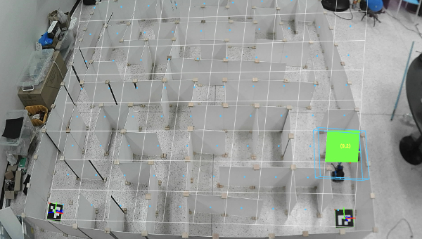
สรุปคือ เราใช้ Marker ID 0 และ 1 เพื่อสร้าง “แกนอ้างอิง” ของแผนที่ และใช้ ID 10 เพื่อระบุตำแหน่งของ “ผู้เล่น” (หุ่นยนต์) ที่อยู่ในแผนที่นั้นๆ
3. บทสรุป (Summary)
รายงานนี้สรุปการอัพเดทสคริปต์ Python สำหรับการติดตามหุ่นยนต์แบบเรียลไทม์โดยใช้เว็บแคม สคริปต์นี้ใช้ ArUco markers เพื่อสร้างระบบพิกัดอ้างอิง โดยมี marker ID 0 และ 1 เป็นตัวกำหนดมุมของแผนที่เสมือน และใช้ ID 10 สำหรับติดตามตำแหน่งของตัวหุ่นยนต์ ระบบสามารถคำนวณและแสดงผลได้ว่าหุ่นยนต์กำลังอยู่ในช่อง (cell) ใดของแผนที่เสมือน
4. คุณสมบัติหลัก (Key Features)
- Real-time Detection: ตรวจจับ ArUco markers จากกล้องแบบเรียลไทม์
- 3D Pose Estimation: คำนวณตำแหน่งและทิศทาง (Pose) 3 มิติของ marker แต่ละตัว
- Dynamic Map Generation: สร้างแผนที่เสมือนแบบไดนามิก โดยอ้างอิงตำแหน่งของ marker 2 ตัว (ID 0 และ 1)
- Robot-to-Grid Mapping: คำนวณตำแหน่งของหุ่นยนต์ (ID 10) และแปลงเป็นพิกัดในแผนที่เสมือน (เช่น ช่องที่ 3, 5)
- Visualization: แสดงผลซ้อนทับบนวิดีโอ ได้แก่:
- วาดเส้นแผนที่เสมือนทั้งหมด
- วาดกล่อง 3 มิติ (Bounding Box) แทนตัวหุ่นยนต์
- ไฮไลท์ช่องของแผนที่เสมือนที่หุ่นยนต์อยู่ พร้อมแสดงพิกัด (cx, cy)
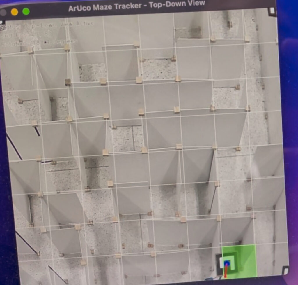
5. ผลลัพธ์และการแก้ไขปัญหา
สรุปคือเป็นไปตามที่คิดไว้ ระบบสามารถระบุตำแหน่งและทิศทางของหุ่นยนต์ได้ แต่ในช่วงแรกพบปัญหาว่า แผนที่เสมือน (Grid) ไม่ตรงกับช่องจริงๆ ในมุมมองของกล้อง จึงได้ทำการแก้ไขมุมหักเหจาก Perspective (Perspective distortion) และปรับภาพให้แสดงผลเสมือนเป็นมุมมองจากด้านบน (Top-Down View) แทน ทำให้ได้ข้อมูลตำแหน่งที่แม่นยำมากขึ้น
นี่คือโค้ดฉบับล่าสุดที่ใช้ในการทดสอบและรายงานผล
import argparse
import time
import os
import cv2
import cv2.aruco as aruco
import numpy as np
# ————————
# Args
# ————————
parser = argparse.ArgumentParser(description=”Aruco detector with grid + robot tracking”)
parser.add_argument(“–cam”, type=int, default=0)
parser.add_argument(“–len”, type=float, default=0.05)
parser.add_argument(“–calib”, type=str, default=”calib.npz”)
parser.add_argument(“–dict”, type=str, default=”DICT_4X4_50″)
parser.add_argument(“–cells”, type=int, default=10)
args = parser.parse_args([])
# ————————
# Dictionary loader
# ————————
DICT_MAP = {name: getattr(aruco, name) for name in dir(aruco) if name.startswith(“DICT_”)}
def load_dictionary(name: str):
if name not in DICT_MAP:
name = “DICT_4X4_50”
return aruco.getPredefinedDictionary(DICT_MAP[name])
# ————————
# Calibration
# ————————
def try_load_calibration(path, frame_size=None):
if os.path.exists(path):
try:
d = np.load(path)
return d[“camera_matrix”].astype(float), d[“dist_coeffs”].astype(float)
except:
pass
w, h = frame_size
fx = fy = 0.9 * max(w, h)
K = np.array([[fx, 0, w/2], [0, fy, h/2], [0, 0, 1]], float)
return K, np.zeros((5, 1), float)
# ————————
# Utils
# ————————
def marker_center_px(c):
c = c.reshape(-1, 2)
return int(c[:, 0].mean()), int(c[:, 1].mean())
# ————————————————————-
# ✅ GRID MATH
# ————————————————————-
def make_grid_from_two_markers(rA, tA, rB, tB, K, dist, cells):
s = args.len
corners = {
‘bl’: np.array([-s/2, -s/2, 0], float),
‘br’: np.array([ s/2, -s/2, 0], float)
}
RA, _ = cv2.Rodrigues(rA)
RB, _ = cv2.Rodrigues(rB)
A_bl = RA @ corners[‘bl’] + tA.reshape(3)
B_br = RB @ corners[‘br’] + tB.reshape(3)
X = (B_br – A_bl)
width = np.linalg.norm(X)
if width < 1e-6:
return None
X = X / width
Y = RA[:, 1]
Y = Y / np.linalg.norm(Y)
cell = width / cells
def proj(pts):
pts = np.asarray(pts, float).reshape(-1, 3)
img, _ = cv2.projectPoints(pts, np.zeros(3), np.zeros(3), K, dist)
return img.reshape(-1, 2)
lines = []
# vertical
for i in range(cells+1):
u = i * cell
p0 = A_bl + X * u
p1 = p0 + Y * width
(x0, y0), (x1, y1) = proj([p0, p1]).astype(int)
lines.append((x0, y0, x1, y1))
# horizontal
for j in range(cells+1):
v = j * cell
p0 = A_bl + Y * v
p1 = p0 + X * width
(x0, y0), (x1, y1) = proj([p0, p1]).astype(int)
lines.append((x0, y0, x1, y1))
return lines, A_bl, B_br, X, Y, cell
# ————————————————————-
# ✅ Point → grid cell
# ————————————————————-
def point_to_grid(A_bl, X, Y, cell, cells, pt):
M = np.column_stack((X, Y))
rhs = (pt – A_bl)
uv, _, _, _ = np.linalg.lstsq(M, rhs, rcond=None)
u, v = uv
cx = int(np.clip(u / cell, 0, cells-1))
cy = int(np.clip(v / cell, 0, cells-1))
return cx, cy
# ————————————————————-
# ✅ Draw grid + cell centers + robot highlight
# ————————————————————-
def draw_grid(img, K, dist, Apose, Bpose, cells, robot_id, id_to_index, rvecs, tvecs):
(rA, tA), (rB, tB) = Apose, Bpose
out = make_grid_from_two_markers(rA, tA, rB, tB, K, dist, cells)
if out is None:
return
lines, A_bl, B_br, X, Y, cell = out
# grid lines
for (x0, y0, x1, y1) in lines:
cv2.line(img, (x0, y0), (x1, y1), (255, 255, 255), 1, cv2.LINE_AA)
# cell centers
for cx in range(cells):
for cy in range(cells):
Pc = A_bl + X * ((cx+0.5)*cell) + Y * ((cy+0.5)*cell)
imgpt, _ = cv2.projectPoints(Pc.reshape(1, 3), np.zeros(3), np.zeros(3), K, dist)
px, py = imgpt.reshape(2).astype(int)
cv2.circle(img, (px, py), 4, (255, 200, 0), -1)
# robot
if robot_id in id_to_index:
idx = id_to_index[robot_id]
pt = tvecs[idx][0].reshape(3)
cx, cy = point_to_grid(A_bl, X, Y, cell, cells, pt)
# polygon of cell
u0 = cx * cell
v0 = cy * cell
P = [A_bl + X*u0 + Y*v0,
A_bl + X*(u0+cell) + Y*v0,
A_bl + X*(u0+cell) + Y*(v0+cell),
A_bl + X*u0 + Y*(v0+cell)]
imgpts, _ = cv2.projectPoints(np.array(P, float), np.zeros(3), np.zeros(3), K, dist)
pts = imgpts.reshape(-1, 2).astype(int)
cv2.fillPoly(img, [pts], (0, 255, 0))
cxm, cym = int(pts[:, 0].mean()), int(pts[:, 1].mean())
cv2.putText(img, f”({cx},{cy})”, (cxm-10, cym+5), cv2.FONT_HERSHEY_SIMPLEX, 0.6, (0,255,255), 2)
# ————————————————————-
# ✅ Robot box drawing (125mm × 130mm × 30mm)
# ✅ FIX — Ensure box is ABOVE marker, not below
# ————————————————————-
def draw_robot_box(img, K, dist, rvec, tvec):
W = 0.125
L = 0.130
H = 0.030
# ✅ FIXED — raise box ABOVE marker instead of below
offset = np.array([0, 0, +H], float)
box = np.array([
[-W/2, -L/2, 0],
[ W/2, -L/2, 0],
[ W/2, L/2, 0],
[-W/2, L/2, 0],
[-W/2, -L/2, H],
[ W/2, -L/2, H],
[ W/2, L/2, H],
[-W/2, L/2, H]
], float)
# ✅ raise whole box
box = box + offset
imgpts,_ = cv2.projectPoints(box, rvec, tvec, K, dist)
pts = imgpts.reshape(-1,2).astype(int)
# top
cv2.polylines(img, [pts[0:4]], True, (255,200,0), 2)
# bottom
cv2.polylines(img, [pts[4:8]], True, (255,200,0), 2)
# edges
for i in range(4):
cv2.line(img, tuple(pts[i]), tuple(pts[i+4]), (255,200,0), 2)
# ————————————————————-
def draw_robot_box(img, K, dist, rvec, tvec):
# robot dimensions (meters)
W = 0.125
L = 0.130
H = 0.030
# shift box downward so the marker is on top
offset = np.array([0, 0, -H], float)
# box corners relative to marker
box = np.array([
[-W/2, -L/2, 0],
[ W/2, -L/2, 0],
[ W/2, L/2, 0],
[-W/2, L/2, 0],
[-W/2, -L/2, -H],
[ W/2, -L/2, -H],
[ W/2, L/2, -H],
[-W/2, L/2, -H]
], float)
box = box + offset
imgpts,_ = cv2.projectPoints(box, rvec, tvec, K, dist)
pts = imgpts.reshape(-1,2).astype(int)
# Draw top rectangle (marker side)
cv2.polylines(img, [pts[0:4]], True, (255,200,0), 2)
# Draw bottom rectangle
cv2.polylines(img, [pts[4:8]], True, (255,200,0), 2)
# Vertical edges
for i in range(4):
cv2.line(img, tuple(pts[i]), tuple(pts[i+4]), (255,200,0), 2)
# ————————————————————-
# MAIN LOOP
# ————————————————————-
aruco_dict = load_dictionary(args.dict)
params = aruco.DetectorParameters()
detector = aruco.ArucoDetector(aruco_dict, params)
cap = cv2.VideoCapture(args.cam)
ret, frame = cap.read()
H, W = frame.shape[:2]
K, dist = try_load_calibration(args.calib, (W, H))
GRID_A_ID = 0
GRID_B_ID = 1
ROBOT_ID = 10
while True:
ret, frame = cap.read()
if not ret:
break
gray = cv2.cvtColor(frame, cv2.COLOR_BGR2GRAY)
corners, ids, _ = detector.detectMarkers(gray)
if ids is not None:
aruco.drawDetectedMarkers(frame, corners, ids)
id_to_index = {int(ids[i][0]): i for i in range(len(ids))}
rvecs, tvecs, _ = aruco.estimatePoseSingleMarkers(corners, args.len, K, dist)
for i in range(len(ids)):
r, t = rvecs[i][0], tvecs[i][0]
cv2.drawFrameAxes(frame, K, dist, r, t, args.len*0.6)
cx, cy = marker_center_px(corners[i]); cv2.circle(frame, (cx, cy), 5, (0,255,0), -1)
# ✅ Grid markers must be detected
if GRID_A_ID in id_to_index and GRID_B_ID in id_to_index:
iA = id_to_index[GRID_A_ID]
iB = id_to_index[GRID_B_ID]
Apose = (rvecs[iA][0], tvecs[iA][0])
Bpose = (rvecs[iB][0], tvecs[iB][0])
robot_id = ROBOT_ID if ROBOT_ID in id_to_index else None
draw_grid(frame, K, dist, Apose, Bpose, args.cells, robot_id, id_to_index, rvecs, tvecs)
# ✅ Draw robot box if robot marker detected
if robot_id is not None:
ridx = id_to_index[robot_id]
rvec_r = rvecs[ridx][0]
tvec_r = tvecs[ridx][0]
draw_robot_box(frame, K, dist, rvec_r, tvec_r)
cv2.imshow(“GRID”, frame)
k = cv2.waitKey(1) & 0xFF
if k == ord(‘q’):
break
cap.release()
cv2.destroyAllWindows()