รายงานความคืบหน้าครั้งที่ 1 (จากเริ่มต้นจนถึงวันที่ 31/10/2025) Class Project (Solve Maze)
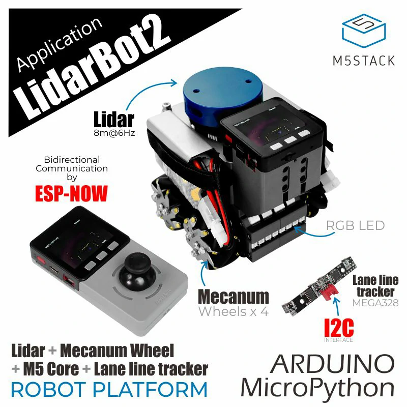
เริ่มต้นได้ทำการศึกษา Hardware และ Software โดยรูปด้านล่างจะเป็นหุ่นยนต์ที่เราจะใช้ในการ solve maze
Hardware list & Spec
1.Lidar Model EAI YDLIDAR X2 LiDAR range and speed: 8m @ 7Hz
2.Remote Control (MCU:M5Core)
3.Robot Control(MCU:M5Core)
4.Batteries (1300mAh @ 11.1V /2Pc.)
5.Robot Led
Product size
142 x 117 x 120mm
Maze size
Maze area 10*10 block (each block has 30*30 cm)
Software
ฝั่งหุ่นยนต์จะใช้เป็น library M5stack การที่จะสื่อสารกับคอมได้ต้อง Micro ROS ที่เป็น library จากการศึกษาและทดลอง compile โค้ด Original ที่ให้มาทาง githup โดยใช้ Arduino IDE พบว่าไม่สามารถ compile code ได้ เนื่องจากหุ่นยนต์เป็นรุ่นเก่าจึงต้อง downgrade board library ของ M5 stack เป็น version 2.1.4 จึงจะสามารถ compile ได้ถึงจะเชื่อมต่อกับทางคอมพิวเตอร์ที่ลง (ROS2 jazzy) เอาไว้เพื่อทำการส่งข้อมูลที่ได้จาก lidar รวมถึงการควบคุม stepper motor ผ่านทางคอมพิวเตอร์
การติดตั้ง Ubuntu และ ROS2 ได้ทำการศึกษาจากเว็บด้านล่าง
https://lungmaker.com/category/library/ros2
File LiDAR Bot Original
Robot Side
โด้ดด้านล่างจะเป็นโค้ดทดสอบการรับและแปลงข้อมูล Lidar
------------------------------------------------------------------------------------------------------------
#include <M5Stack.h>
#include "lidarcar.h" // เราใช้คลาสนี้เป็นไดรเวอร์
#include "RprTrack.h" // จำเป็นสำหรับ lidarcar.h
LidarCar lidarcar;
unsigned long lastPrintTime = 0;
const long printInterval = 1000; // พิมพ์ทุก 1 วินาที
// =================================================================
// SETUP
// =================================================================
void setup() {
M5.begin(true, false, false, true);
M5.Power.begin();
// Serial Monitor (USB)
Serial.begin(115200);
Serial.println("");
Serial.println("============================");
Serial.println(" LidarPP Driver Test ");
Serial.println("============================");
// Serial2: พอร์ตสำหรับมอเตอร์ (จำเป็นสำหรับ lidarcar.Init())
Serial2.begin(115200);
// Serial1: พอร์ตสำหรับ Lidar
Serial.println("Using: 230400 baud, Pins 16, 2");
Serial1.begin(230400, SERIAL_8N1, 16, 2);
// ------------------------------------
// เริ่มต้นการทำงานของมอเตอร์และ LED
lidarcar.Init();
Serial.println("Setup complete. Waiting for LiDAR data...");
}
// =================================================================
// LOOP
// =================================================================
void loop() {
M5.update();
// ฟังก์ชันนี้ (ใน LidarCar.cpp) จะเรียก GetData()
// เพื่ออัปเดตอาร์เรย์ lidarcar.distance[]
lidarcar.MapDisplay();
// ตรวจสอบว่าถึงเวลาพิมพ์ข้อมูลหรือยัง (ทุก 1 วินาที)
unsigned long currentTime = millis();
if (currentTime - lastPrintTime >= printInterval) {
lastPrintTime = currentTime;
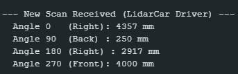
Serial.println("\n--- New Scan Received (LidarCar Driver) ---");
// พิมพ์ค่าระยะทาง 4 มุม (distance[] มี 360 จุด)
Serial.print(" Angle 0 (Right): "); //ของเดิม Front
Serial.print(lidarcar.distance[0]); // จุดที่ 0
Serial.println(" mm");
Serial.print(" Angle 90 (Back) : "); //ของเดิม Left
Serial.print(lidarcar.distance[90]); // จุดที่ 90
Serial.println(" mm");
Serial.print(" Angle 180 (Right) : "); //ของเดิม Back
Serial.print(lidarcar.distance[180]); // จุดที่ 180
Serial.println(" mm");
Serial.print(" Angle 270 (Front): "); //ของเดิม Right
Serial.print(lidarcar.distance[270]); // จุดที่ 270
Serial.println(" mm");
}
delay(1);
}
------------------------------------------------------------------------------------------------------------ค่าที่ได้จากการแปลง
โด้ดด้านล่างจะเป็นโค้ดทดสอบการควบคุม Motor ผ่าน ROS
--------------------------------------------------------------------------------------------------------------------
 * LidarBotROS (Motor Test Only Version)
 * This sketch is simplified to *only* control the motors via ROS.
 * 1. All LiDAR publishing code (/scan, X2driver, Serial1) is disabled.
 * 2. All Time Sync code is disabled.
 * 3. It only Subscribes to /cmd_vel to control motors.

// --- Standard Libraries ---
#include <M5Stack.h>
#include <Preferences.h> // For original Master.ino compatibility

// --- micro-ROS Libraries ---
#include <WiFi.h>
#include <micro_ros_arduino.h>
#include <rcl/rcl.h>
#include <rclc/rclc.h>
#include <rclc/executor.h>
// #include <sensor_msgs/msg/LaserScan.h> // (LiDAR Disabled)
#include <geometry_msgs/msg/Twist.h>   // For Motor Subscriber

// --- Project-Specific Libraries ---
// #include "mapData.h"      // (LiDAR Disabled)
// #include "X2driver.h"     // (LiDAR Disabled)
#include "lidarcar.h"   // (Motor Control is needed)
// #include "lock.h"         // (LiDAR Disabled)
// #include "doProcess.h"    // (LiDAR Disabled)

// =================================================================
// Global Variables
// =================================================================

// --- WiFi & ROS Agent ---
const char* WIFI_SSID = "Galaxy S24 FE";
const char* WIFI_PASS = "A1234567";
const char* AGENT_IP = "10.98.248.201 "; // IP ของคอมที่รัน Agent
const uint16_t AGENT_PORT = 8888;

// --- micro-ROS Components ---
rclc_executor_t executor;
rclc_support_t support;
rcl_allocator_t allocator;
rcl_node_t node;
// rcl_timer_t timer;                     // (LiDAR Disabled)
// rcl_publisher_t publisher;             // (LiDAR Disabled)
rcl_subscription_t subscription;       // Subscription for /cmd_vel
// sensor_msgs__msg__LaserScan scan_msg;  // (LiDAR Disabled)
geometry_msgs__msg__Twist twist_msg;   // Message for Motor data

// --- Project Objects ---
// X2 lidar;                          // (LiDAR Disabled)
LidarCar lidarcar;                 // Motor Controller

// (Semaphore Disabled)
// SemaphoreHandle_t xSemaphore = xSemaphoreCreateMutex();

// (LiDAR Disabled)
// void updateData(void *buf) { (void)buf; }


// =================================================================
// micro-ROS Callback (Motor Control)
// =================================================================
// This function is called every time a new message arrives on /cmd_vel
void subscription_callback(const void * msin)
{
  const geometry_msgs__msg__Twist * msg = (const geometry_msgs__msg__Twist *)msin;

  // Convert ROS Twist (meters/sec, radians/sec) to LidarCar format (-7 to 7)
  const float max_linear_speed = 0.5; // m/s
  const float max_angular_speed = 1.0; // rad/s

  // 1. Angular (Rotation) - X value in LidarCar
  int8_t motor_x = (int8_t)( (msg->angular.z / max_angular_speed) * -7.0 );

  // 2. Linear (Forward/Backward) - Y value in LidarCar
  int8_t motor_y = (int8_t)( (msg->linear.x / max_linear_speed) * 7.0 );

  // 3. Strafe (Left/Right) - X value in LidarCar *with A=1*
  int8_t motor_strafe = (int8_t)( (msg->linear.y / max_linear_speed) * 7.0 );

  byte motor_a = 0; // Normal mode (Forward/Rotate)

  if (abs(motor_strafe) > abs(motor_x)) {
    motor_x = motor_strafe;
    motor_a = 1; // Set to Strafe mode
  }

  lidarcar.ControlWheel(motor_x, motor_y, motor_a);
}

// =================================================================
// (LiDAR Publisher Callback Disabled)
// =================================================================
// void timer_callback(...) { ... }


// =================================================================
// (LiDAR Helper Function Disabled)
// =================================================================
// void setupLaserScanMessage() { ... }


// =================================================================
// SETUP
// =================================================================
void setup() {
  // Start M5Stack core
  M5.begin(true, true, false, true); // (LCD, SD, Serial, I2C)
  M5.Power.begin();

  // Serial Monitor for debugging (USB)
  Serial.begin(115200);

  // (LiDAR Port Disabled)
  // Serial1.begin(115200, SERIAL_8N1, 16, 17);

  // Serial2: The port for the Motor Controller Board
  Serial2.begin(115200);

  Serial.println("============================");
  Serial.println(" LidarBotROS (Motor Test Only) ");
  Serial.println("============================");

  // --- 1. Connect to WiFi & Agent ---
  Serial.print("Connecting to WiFi: ");
  Serial.println(WIFI_SSID);

  set_microros_wifi_transports((char*)WIFI_SSID, (char*)WIFI_PASS, (char*)AGENT_IP, AGENT_PORT);
  delay(1000); // Give WiFi time to connect

  Serial.print("Pinging Agent (");
  Serial.print(AGENT_IP);
  Serial.print(")...");

  // Ping agent
  while(RMW_RET_OK != rmw_uros_ping_agent(1000, 1)){
    Serial.print(".");
    delay(500);
  }
  Serial.println("\nAgent connected!");

  // --- 2. (Time Synchronization Disabled) ---

  // --- 3. Initialize micro-ROS Components ---
  allocator = rcl_get_default_allocator();

  // We only need 1 handle (for the Motor Subscriber)
  rclc_support_init(&support, 0, NULL, &allocator);
  rclc_node_init_default(&node, "m5stack_motor_node", "", &support);

  // --- 4. (Create Publisher Disabled) ---

  // --- 5. Create Subscriber (Motor) ---
  rclc_subscription_init_default(
    &subscription,
    &node,
    ROSIDL_GET_MSG_TYPE_SUPPORT(geometry_msgs, msg, Twist),
    "cmd_vel"
  );

  // --- 6. (Create Timer Disabled) ---

  // --- 7. Create Executor (Handles 1 task) ---
  rclc_executor_init(&executor, &support.context, 1, &allocator); // Only 1 handle
  // rclc_executor_add_timer(&executor, &timer); // (LiDAR Disabled)
  rclc_executor_add_subscription(&executor, &subscription, &twist_msg, &subscription_callback, ON_NEW_DATA);

  // --- 8. (Allocate LiDAR memory Disabled) ---

  Serial.println("Setup complete. micro-ROS node is spinning.");
  Serial.println("Subscribing: /cmd_vel (Twist)");
  Serial.println("Publishing: /scan (DISABLED)");
}

// =================================================================
// LOOP
// =================================================================
void loop() {
  M5.update();

  // (LiDAR read Disabled)
  // while(Serial1.available()) { ... }

  // Spin the micro-ROS executor
  rclc_executor_spin_some(&executor, RCL_MS_TO_NS(10));

  delay(10); // Changed from 1ms to 10ms
}
--------------------------------------------------------------------------------------------------------------------
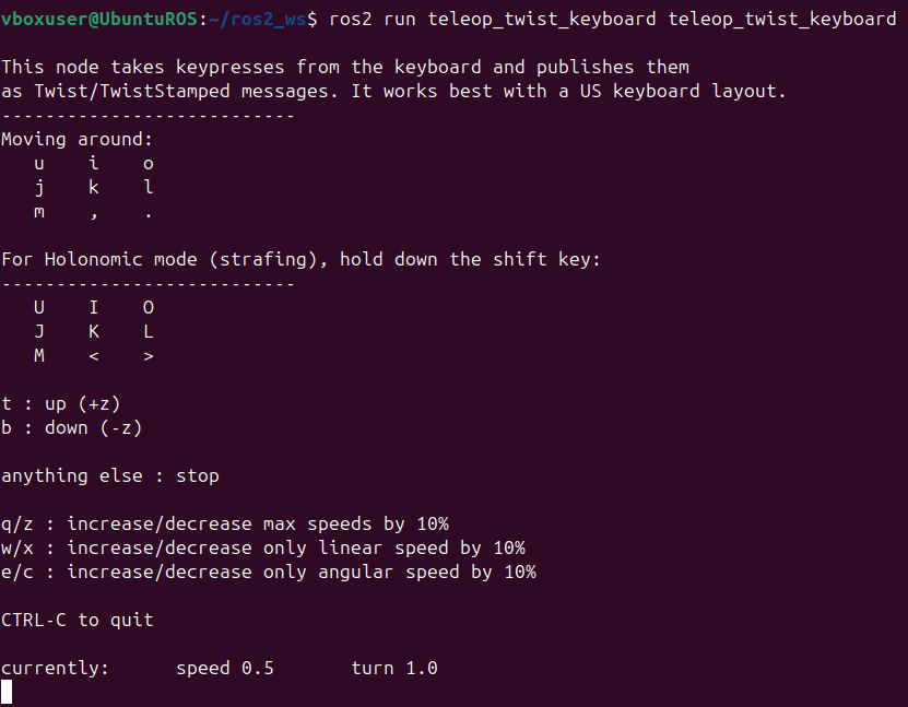
ตัวอย่างหน้าจอควบคุมแบบ Manual ผ่าน ROS2 ในคอมพิวเตอร์
ปัญหาที่พบ 06/11/2568
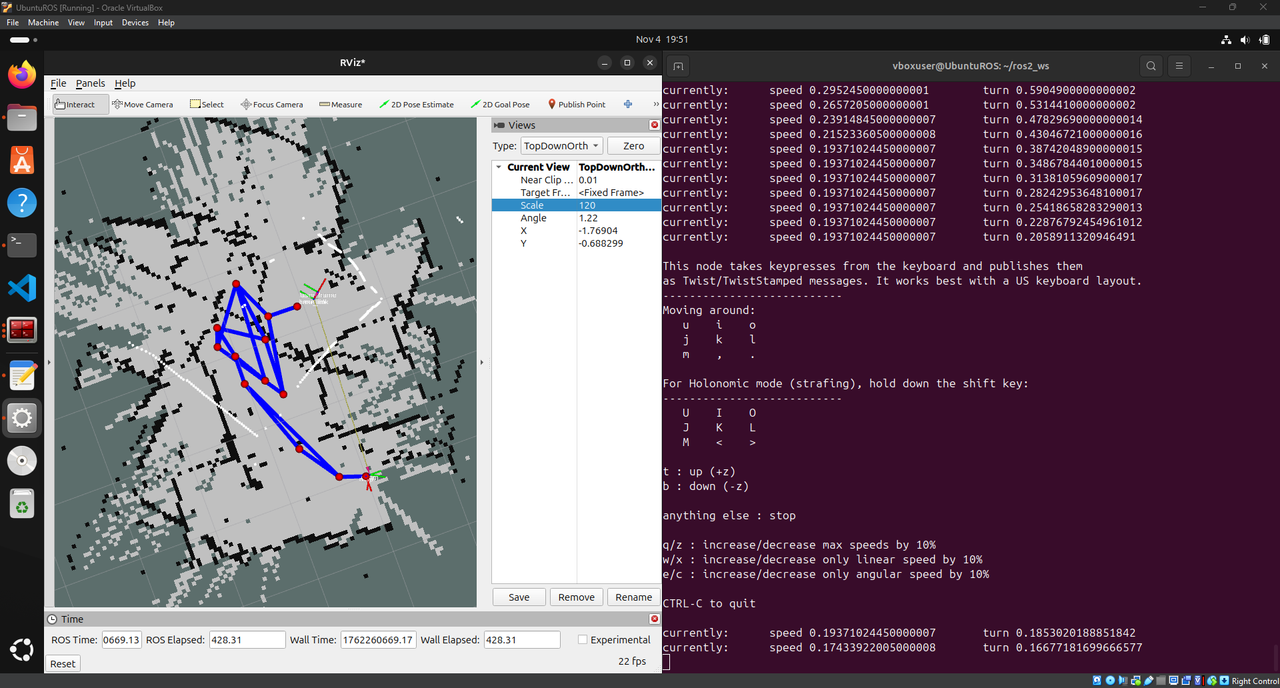
ตอนนี้สามารถดึงค่า Lidar จาก Lidar bot มาสร้าง map โดยใช้เครื่องมือที่เรียกว่า slam มาสร้าง map ได้แล้วแต่ map ที่ได้มีความบิดเบี้ยวสันนิษฐานว่าอาจเกิดจาก noise ที่ตัว Lidar(ทดลองวางหุ่นอยู่กับที่แต่ค่า lidar วิ่งไม่เท่าเดิมทำให้ map เพี้ยน) จึงจะลองใช้ IMU เข้ามาฟิวชั่นช่วยเพื่อให้ map มีความสมบูรณ์และแม่นยำมากขึ้นแต่ปัญหาที่เจอคือ MicroROS ไม่สามารถ sync time กับ ROS ได้ยังไม่ทราบสาเหตุทดลองเปลี่ยน Router ปิด firewall ทั้งหมดแล้วก็ยังไม่หายใน githup พบว่ามีอาการคล้ายๆกันแต่ลองแก้ตามแล้วก็ยังไม่หาย ทำให้สร้าง map ได้ไม่สมบูรณ์ไม่สามารถส่งไป Nav2 ที่เป็นเครื่องมือในการหา Path ในการวิ่งในรอบ2ต่อได้
ตอนนี้สิ่งที่ทำได้แล้วคือ 1.ควบคุมหุ่นผ่าน Computer(ROS) 2.รับค่า Lidar 3.รับค่า IMU
รายงานความคืบหน้าครั้งที่ 2 (จากเริ่มต้นจนถึงวันที่ 09/11/2025)
จากการปรึกษากันภายในทีมได้ทางเลือกใหม่คือจะใช้กล้องในการเช็คหาตำแหน่งของรถว่าอยู่ส่วนไหนของ Maze ดังนั้นในส่วนที่ผมจะเริ่มทำต่อไปคือการพยายามให้รถอยู่กึ่งกลางของช่องและค้นหากำแพงรวมถึงพยายาม Control ไม่ให้รถชนกำแพง
ตัวอย่างโค้ด:
void LidarCar::MapDisplay(void){

  M5.Lcd.setCursor(0, 0, 2);
  M5.Lcd.print(dataLength);
  M5.Lcd.print("D/");
  M5.Lcd.print(lidarSpeed);
  M5.Lcd.print("S/");
  M5.Lcd.print(packCount);


  for(int i = 0; i < 45; i++)
  {
    //Cortrol_flag
    if (showAngle >=  359){
       Cortrol_flag = true;
       count++;
    }

    if(showAngle >= 359)
      showAngle = 0;
    else
      showAngle++;
    //Serial.print("showAngle = ");Serial.println(showAngle);
    // distance[showAngle]
    disX[showAngle] = ( 80 + (distance[showAngle] / 70) * cos(3.14159 * showAngle / 180 + 0.13))*2;
    disY[showAngle] = (100 + (distance[showAngle] / 70) * sin(3.14159 * showAngle / 180 + 0.13))*2;
    //!แสดงผลที่จอ
    M5.Lcd.drawPixel(oldDisX[showAngle] , oldDisY[showAngle], BLACK);
    if(distance[showAngle] == 250)
      M5.Lcd.drawPixel(disX[showAngle] , disY[showAngle], BLUE);
    else
      M5.Lcd.drawPixel(disX[showAngle] , disY[showAngle], YELLOW);
    oldDisX[showAngle] = disX[showAngle];
    oldDisY[showAngle] = disY[showAngle];

    //Serial.print(" distance[showAngle] = ");Serial.print(distance[showAngle]);Serial.print(" disX[showAngle] = ");Serial.print(disX[showAngle]);Serial.print(" disY[showAngle] = ");Serial.println(disY[showAngle]);
    #if 1
    mapdata[i * 4 + 0] = showAngle / 256;
    mapdata[i * 4 + 1] = showAngle % 256;
    mapdata[i * 4 + 2] = distance[showAngle] / 256;
    mapdata[i * 4 + 3] = distance[showAngle] % 256;
    #else
    mapdata[i * 4 + 0] = 233;
    mapdata[i * 4 + 1] = 233;
    mapdata[i * 4 + 2] = 236;
    mapdata[i * 4 + 3] = 236;
    #endif

	  //เช็คความถูกต้อง lidar
	  if((showAngle >= 180) && (showAngle <= 360)){
      if((distance[showAngle] == 250)||(distance[showAngle] == 0)||(distance[showAngle] >= 10000))
      {
         Dis[showAngle - 180][0] = 0;
         Dis[showAngle - 180][1] = 0;
      }
      else
      {
        Dis[showAngle - 180][0] = disX[showAngle];
        Dis[showAngle - 180][1] = disY[showAngle];
      }
     }

   }

  //รับข้อมูล Lidar
  GetData();

}
//! โหมดเดินตามเส้น
void LidarCar::CarMaze(void){
if((Cortrol_flag) && (count >= 10))
  {
   CarCortrol();
   Cortrol_flag = false;
   count = 10;
  }
  if((count >= 10))
    ControlWheel(motor_out, motor_y_out, 0);
}
//! การประมวลผลเขาวงกต
void LidarCar::CarCortrol(void)
{
    //! ประเมินระยะห่าง ซ้าย ขวา หน้า
    float left_line = 0,right_line = 0,front_line = 0;
    int buf = 0;

    // ... (โค้ดคำนวณระยะทาง) ...

    //! ระยะห่างด้านซ้าย
    left_line = (float)buf/count;

    // ... (โค้ดคำนวณระยะทาง) ...

    //! ระยะห่างด้านหน้า
    front_line = (float)buf/count;

    // ... (โค้ดคำนวณระยะทาง) ...

    //! ระยะห่างด้านขวา
    right_line = buf /count;

    //! การคำนวณ PID
    * สูตรการคำนวณ PID คือ
    * out = kp * error + kd * (error - last_error)
    * ณ ที่นี้ ใช้เพียงค่า kp เท่านั้น, โหมด kd เป็น 0, สามารถลองเพิ่มค่า kd ได้
    * แนวคิดพื้นฐานของ PID: [ลิงก์] http://blog.sina.cn/dpool/blog/s/blog_80f7b8e90101ikk8.html?md=gd
    */

    //! ปรับค่า kp โดยใช้ระยะห่างซ้ายขวา
    float kp = 0.4;motor_y_out = 7;
    if((right_line <= 1.0) || (left_line <= 1.0))
    {
      kp = 1;
      motor_y_out = 4;
    }
    if((front_line >= 170.0) || (front_line <= 1.0))
    {
      kp = 1;
      motor_y_out = 3;
    }

    //! คำนวณค่าเบี่ยงเบนตำแหน่งของเส้นทางปัจจุบัน
    float error_line = (left_line + right_line)/2.0 - 157.80;
    if((left_line == 0) || (right_line == 0))error_line = last_error_line;
    last_error_line = error_line;

    int ret = 0;
    //! ตรวจสอบว่าเป็นทางตันหรือไม่
    ret = MazaCom(error_line ,left_line,right_line,front_line) ;
    if(!ret){
      if(go_flag)
    motor_out =  -kp  * error_line/2;
    else
    motor_out =  kp  * error_line;
    //! สัญญาณเอาต์พุต (การเลี้ยว)
    if(motor_out >= 4.0)motor_out = 4.0;
    else if(motor_out <= -4.0)motor_out = -4.0;
    ControlWheel(motor_out,motor_y_out, 0);
    }
}
//! ตรวจจับทางตัน, ตรวจสอบว่าข้างหน้าไม่มีทางไป, ให้กลับตัว
int LidarCar::MazaCom(float error_line,float left_line,float right_line,float front_line)
{
   // ... (โค้ดตรวจจับทางตัน) ...
}
รวบรวมข้อมูล Lidar:
- ฟังก์ชัน
MapDisplay(void)จะประมวลผลข้อมูลดิบจาก Lidar - ข้อมูลระยะทางจาก Lidar ในช่วงมุม 180 ถึง 360 องศา (ด้านหน้าและด้านข้างของหุ่นยนต์) จะถูกเก็บไว้ในอาร์เรย์
Disเพื่อใช้ในการคำนวณ
คำนวณระยะห่างจากกำแพง:
- ในฟังก์ชัน
CarCortrol(void)หุ่นยนต์จะคำนวณระยะห่างโดยเฉลี่ยจากกำแพง 3 ด้าน:left_line: ระยะห่างเฉลี่ยด้านซ้าย (จากข้อมูล Lidar มุม 180-234 องศา)front_line: ระยะห่างเฉลี่ยด้านหน้า (จากข้อมูล Lidar มุม 235-284 องศา)right_line: ระยะห่างเฉลี่ยด้านขวา (จากข้อมูล Lidar มุม 285-360 องศา)
มีการคำนวณ “ค่าความผิดพลาด” (error_line) เพื่อดูว่าหุ่นยนต์อยู่ใกล้หรือไกลจากจุดกึ่งกลางมากแค่ไหน: float error_line = (left_line + right_line)/2.0 - 157.80;
ใช้ค่า error_line นี้ใน Proportional Controller (P-Controller) ซึ่งเป็นส่วนหนึ่งของระบบ PID (ในโค้ดนี้ใช้แค่ P) เพื่อคำนวณการเลี้ยว (motor_out): motor_out = -kp * error_line/2; (ค่า kp คือค่า gain)
การตรวจจับและจัดการทางตัน (Dead End):
- ฟังก์ชัน
MazaCom()ถูกเรียกใช้เพื่อตรวจสอบว่าข้างหน้าเป็นทางตันหรือไม่ - เงื่อนไขการตรวจจับทางตันคือ:
- หุ่นยนต์อยู่ค่อนข้างตรงกลาง (
abs(error_line) <= 4.0) - มีสิ่งกีดขวางด้านหน้าในระยะใกล้ (
front_line >= 180.0) - มีกำแพงอยู่ทั้งด้านซ้ายและขวา (
(right_line <= 190) || (left_line >= 120.0))
- หุ่นยนต์อยู่ค่อนข้างตรงกลาง (
- หากตรวจพบทางตัน หุ่นยนต์จะ หยุด ชั่วขณะ (
motor_out = 0,motor_y_out = 0) จากนั้นจะเริ่ม หมุนตัวกลับ (โดยตั้งค่าmotor_out = 1,motor_y_out = 0เพื่อให้หุ่นยนต์หมุน)
ควบคุมมอเตอร์:
- ค่า
motor_out(การเลี้ยว) และmotor_y_out(การเคลื่อนที่หน้า/หลัง) ที่คำนวณได้ จะถูกส่งไปยังฟังก์ชันControlWheel()เพื่อควบคุมความเร็วมอเตอร์ล้อทั้งสี่ให้หุ่นยนต์เคลื่อนที่ไปตามทิศทางที่กำหนด