Members
- Peeradon Ruengkaew
- Tuchapong Sangthaworn
- Pongpat wongkamhaengharn
Objective
Objective 1: Auto-mapping an Unknown Maze Environment
- Implement systematic exploration: Design a navigation strategy where the robot moves forward and turns right to ensure complete task by find out goal of the maze.
- Generate a real-time map: Use LiDAR sensors to gather spatial data and represent the maze structure as a 2D occupancy grid.
- Avoid obstacles and dead ends: Develop logic for the robot to detect and avoid obstacles while exploration
Objective 2: Solving the Maze
- Use path planning algorithms: Implement a suitable algorithm (e.g., A*, Dijkstra) to calculate the shortest or optimal path to the goal.
- Enable robot-computer communication:
- Use a communication protocol (e.g., ROS topics, services) to allow the robot to transmit local sensor data to localize respect to the generated map.
- Ensure the computer calculated solution path and sends back robot command to achieve the goal.
- Optimize execution of the solution path: Develop strategies for smooth and efficient movement along the planned path.
Scope
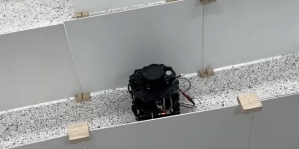
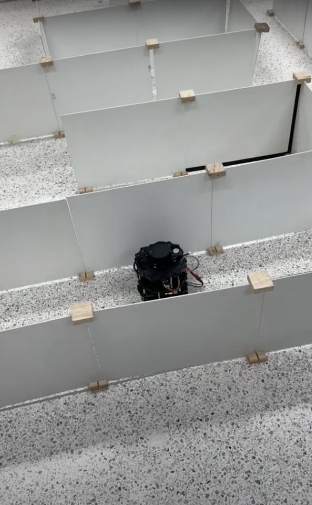
- The maze has a dimension of 3000 × 3000 mm or consists of 10 × 10 blocks.
- The LidarBot will navigate the maze in two rounds:
- First Round: Mapping the Maze
- The LidarBot will explore the entire maze, generating a complete map during its first traversal.
- It will systematically move through the maze, detecting and avoiding obstacles while ensuring comprehensive coverage of all pathways.
- Second Round: Finding the Shortest Path
- Using the map created in the first round, the LidarBot will calculate the shortest path from the start point to the maze exit.
- The robot will navigate the maze efficiently along the calculated path, demonstrating the shortest solution to exiting the maze.
- First Round: Mapping the Maze
System Overview
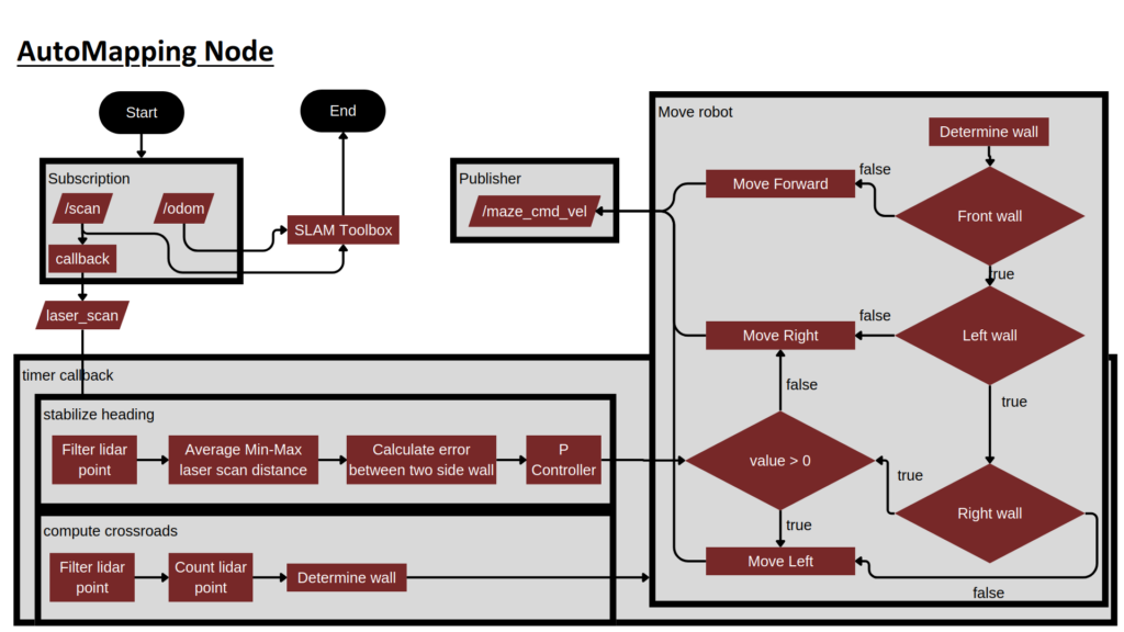
Autonomous Slam Moving Right Wall Follower
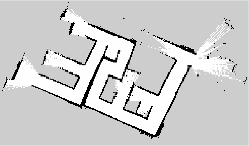
Mapping
Explanation Code
Overview
document for Auto-mapping an Unknown Maze Environment using right wall follower algorithm for maze size 10*10
Key Parameters
Distance Thresholds
- Front Wall Distance: 0.38 meters
- Side Wall Distance: 0.44 meters
- Wall Detection Threshold: 20 points
Scanner Ranges
- Front scan: 0-15° and 345-360°
- Left scan: 30-120°
- Right scan: 240-330°
- Back left scan: 110-140°
- Back right scan: 220-250°
Key Functionalities
1. Crossroad Detection
The system detects crossroads by analyzing laser scan data in different directions:
- Monitors front, left, and right walls
- Considers a crossroad when specific wall patterns are detected
- Uses point count thresholds to determine wall presence
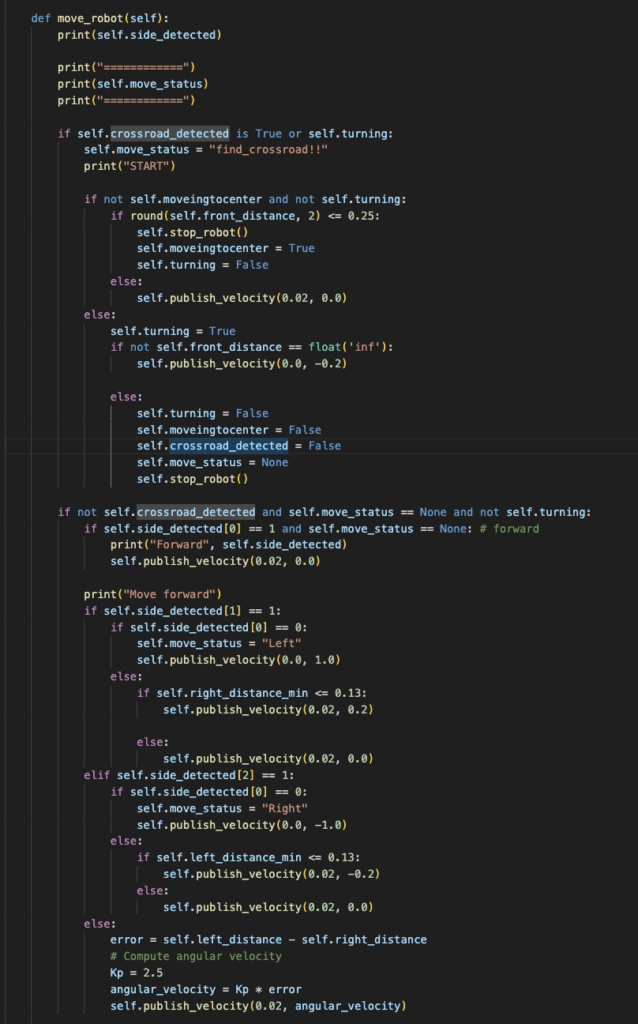
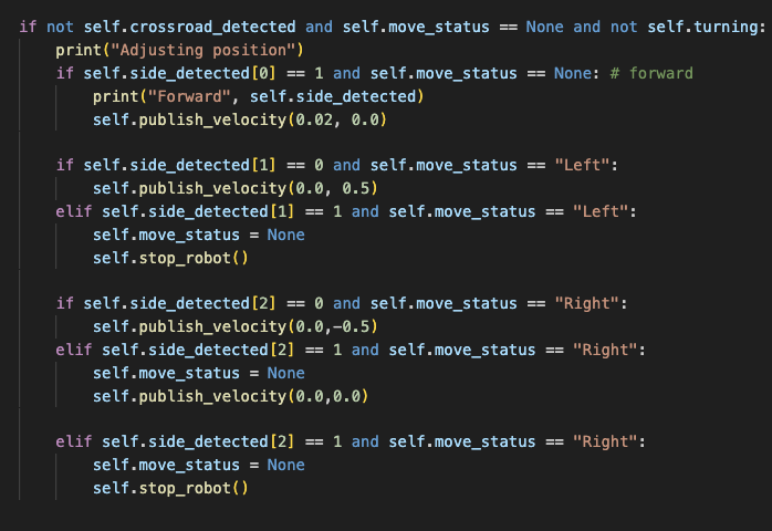
2. Movement Control
Implements several movement behaviors:
- Normal Movement
- Wall following with proportional control
- Error-based angular velocity adjustment
- Kp value: 2.5
- Crossroad Navigation
- Two-phase approach:
- Center positioning (moves to 0.25m from front wall)
- Rotation until clear path detected
- Obstacle Avoidance
- Reactive turning based on wall detection
- Separate handling for left and right obstacles
Control Flow
Main Loop (50Hz)
- Processes laser scan data
- Updates crossroad detection status
- Executes movement control
- Publishes velocity commands
State Management
Maintains several state flags:
handling_crossroadmovingturningmoveingtocenterleft_turning
Safety Features
- Emergency Stop
- Implements stop_robot() function
- Called during shutdown
- Used in error conditions
- Data Validation
- Checks for valid laser scan data
- Validates odometry messages
- Handles missing data gracefully
Limitations
Fixed threshold values may need adjustment for different environments
Simple proportional control might not handle all scenarios
Scenario 1: Crossroad Detected
• self.crossroad_detected = True
1. Moves to the center of the crossroad.
2. Turns right until no obstacle is detected in the front.
Scenario 2: Obstacle Ahead
• self.side_detected = [0, 1, 1]
• Turns left or right based on side distances to avoid the obstacle.
Scenario 3: Wall Following
• self.side_detected = [1, 1, 0]
• Adjusts its direction using proportional control to follow the wall on its left.
Video Auto slam
Slove Maze
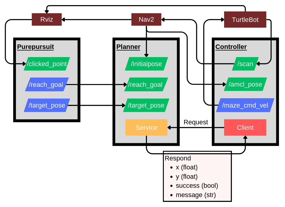
Global Path
using NavFn Planner (link: https://docs.nav2.org/configuration/packages/configuring-navfn.html) using A* search algorithm.
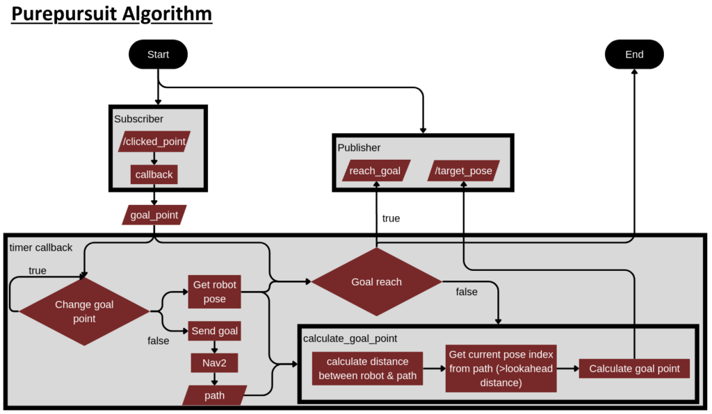
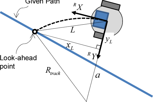
Purepusuit algorithm
use to select reference point from global path by using look-ahead distance as a requirement.
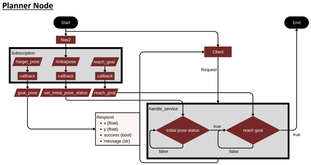
Planner
use as a server that receive and known global path, then it will receive reference point (use purepusuit algorithm) from global path to respond for client or Controller Node when the client request.
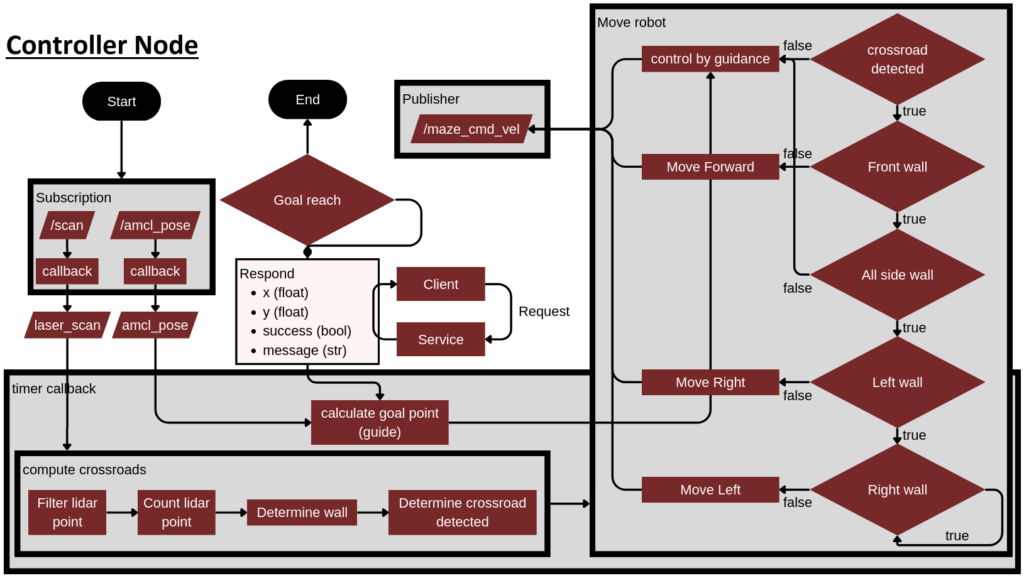
Controller
use as a client to request reference point when it fond crossroad.
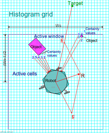
Obstacle Avoidance Algorithm
Virtual Force Field (VFF)
Consist of three vector:
- Attractive vector point towards the waypoint.
- Repulsive vector point opposite direction of obstacle (summing all the vectors that are translated from the sensor readings).
- Final vector summing the attractive and repulsive vector.
Problem with maze-solving:
- Repulsive vectors often push the robot away from doorways, preventing successful passage through openings
- Repulsive vectors tend to cause oscillating left-right movements, making it difficult for the robot to maintain a steady path
- These issues commonly occur because the repulsive forces from walls on both sides create a balanced opposition of force
- The robot may get stuck in local minima, especially in narrow corridors
Wall detection by lidar data
Consist of three component:
- Filter point within wall distance threshold from lidar data.
- Count point within wall distance threshold from lidar data.
- Determine wall based on the count threshold.
- Determine crossroad detected based on number of wall detected.
Consist of two parameter:
- WALL DISTANCE THRESHOLD filter to capture only within distance threshold lidar data.
- WALL THRESHOLD threshold for detecting a wall based on point count.
Problem with maze-solving:
- Require to tuning threshold parameters that suit with the task.
- Robot heading better to be aligned with the wall to perform wall detection correctly.
Heading stabilization algorithm
Robot heading stabilization by lidar data (align with wall)
Consist of two component:
- Lidar Observation Point range of lidar data view and average of min and max data to represent as the error distance from robot to that wall side.
- PID controller correct error between two side wall distance and robot heading
Consist of two parameter:
- Kp constant proportional gain.
- Laser Distance Filter laser distance threshold from lidar data.
- Laser Detect Angle based on the count threshold.
Problem with maze-solving:
- Require state machine to select operating time only when robot need to exploring straight through wall and align with two side wall.
- If robot operate at the corner that need hard turn left-right it might rarely successful turning.
Code Structure
Purepusuit algorithm
- Initialize
- ActionClient:
- ComputePathToPose
- Subscription:
- /clicked_point
- Publisher:
- /reach_goal
- /target_pose
- /goal_marker
- TF2 Buffer
- Timer Loop
- Parameters:
- Look-ahead Distance
- Goal Threshold
- dt
- ActionClient:
- Timer Loop
- Check if the final goal change then change the global path.
- Retrieve the robot’s current pose from AMCL (Nav2).
- Check if get robot’s pose do pure pursuit calculation.
- Check if Reach Goal publish topic /reach_goal if reach goal.
- Check if path exists and current pose index (look ahead point) inside number of path index.
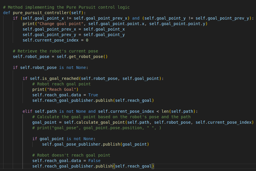
- Calculate goal point based on look ahead distance then publish /target_pose (Figure 1).
- publish topic /reach_goal doesn’t reach goal (Figure 2).
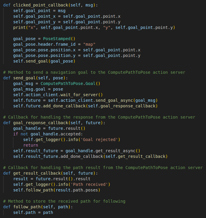
- Select Goal Point & receive path from Nav2
- Subscribe goal point from topic /clicked_point then send goal point to Nav2.
- Receive path from Nav2 response then save path in self.path.
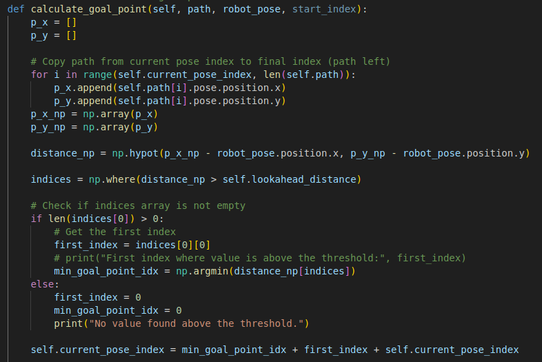
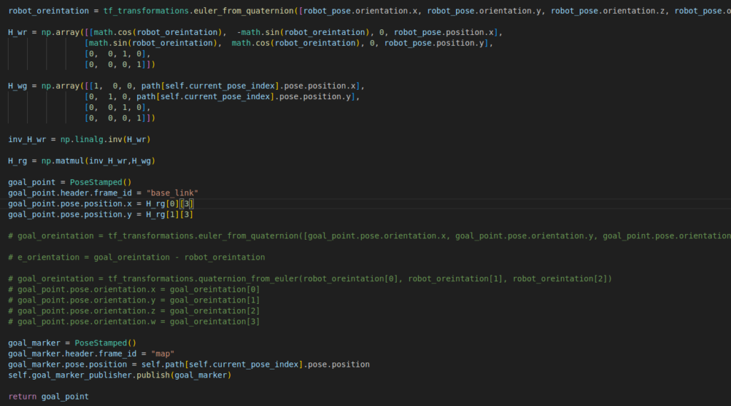
- Calculate Goal Point from path
- Copy path from current pose index to final index (path left).
- Choose next step goal pose index by look-ahead distance.
- Set current pose index as next step goal pose.
- Check is Goal Reached
- calculate by euclidean distance distance between robot and goal pose.
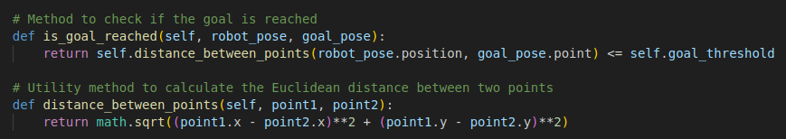
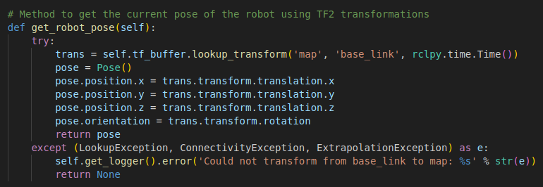
- Get Robot Pose
- Use TF2 transformations lookup_transform from map to base link
Planner Node
- Initialize
- Service:
- get point
- Subscription:
- /target_pose
- /reach_goal
- /initialpose
- BasicNavigator (Nav2 Api)
- Parameters:
- Look-ahead Distance
- Goal Threshold
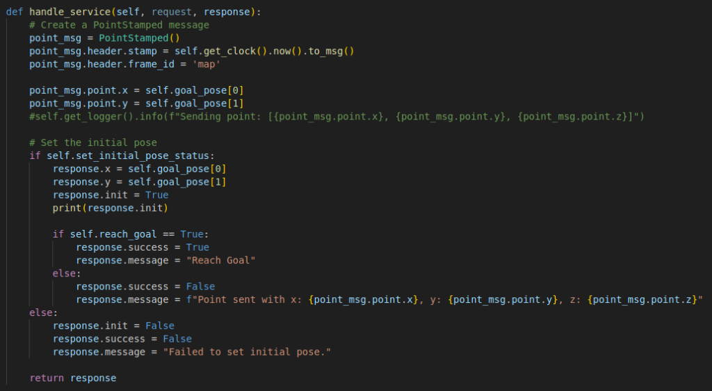
- Service:
- Handle Service
- Create a PointStamped message for current guiding pose.
- Check robot has been set the initial pose.
- Check robot has been reach final goal pose. If not response current guiding pose.

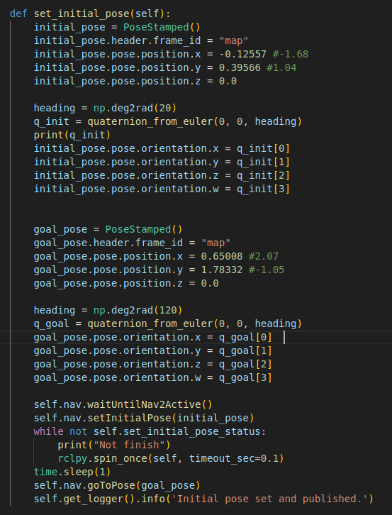
- Set Robot initial pose in Rviz.
- Create a PoseStamped message for initial robot pose.
- Create a PoseStamped message for final goal pose (or you can comment this part and use subscribe /click_point as you can get from purepusuit algorithm).
- Use Nav2 to set robot initial pose and find path to final goal pose.
Controller Node
- Initialize
- Client:
- get point
- Publisher
- /maze_cmd_vel
- /odom
- Subscription:
- /scan
- /amcl_pose
- Timer Loop
- Parameters:
- vx & omega maximum
- SIDE WALL DISTANCE THRESHOLD
- FRONT WALL DISTANCE THRESHOLD
- WALL_THRESHOLD (count of point detected at wall)
- Client:
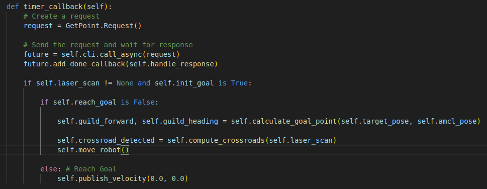
- Timer Loop
- Request guiding pose from Planner node.
- Check initial status (get lidar information & rviz init robot).
- Calculate guiding forward and heading.
- Check is crossroad detected.
- Command robot.
- Check if robot reach goal stop robot.
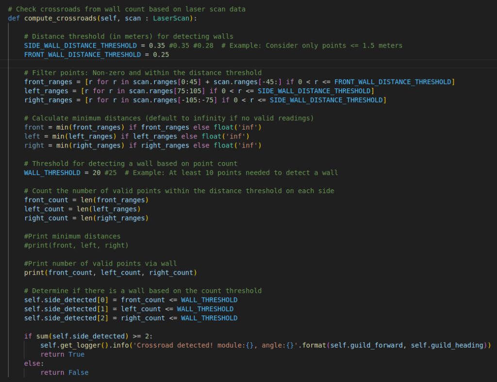
- Compute crossroad detect
- Filter non-zero points and within the wall distance threshold from lidar data.
- Count the number of valid points within the distance threshold on each side.
- Determine if there is a wall based on the count threshold.
- Check if crossroad detected.
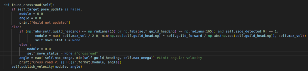
- Calculate command control robot
- Check if crossroad detected use guiding forward and heading to command robot.
- Check if no wall in front move forward with constant value.
- If there is wall in front
- check left and right side if found wall use guiding forward and heading to command robot.
- check left or right side if found wall rotate in the opposite side with constant value.
- Continue rotate if last time step it rotate in that same way.

- Command robot using guiding forward and heading
- Check if the value is not updated stop robot.
- Calculate heading error if below threshold only rotate robot first.
- Publish robot velocity command.
- Handle Service
- Receive current guiding pose.
- Receive initialize , reach goal and target pose update status.
Video Maze-Solving
How to run code
https://github.com/S-Tuchapong/Mobile-Robot-For-Maze-Solving
video solve maze 1*