26/3/2024
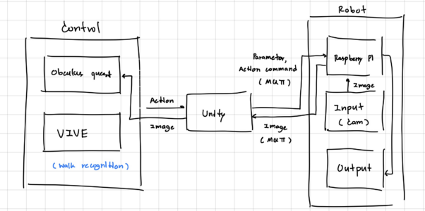
Design of overall flow diagram
The robot is control using VR consist of Obculus quest for controlling the movement of camera on robot and VIVE which tracking the action and movement of body for controlling movement of robot. The action of human was send to the Unity and transfer to action command and parameters which will send to single board computer, using MQTT protocal for taking an action of robot while have a camera for collect environment and send the image (video) to user through Unity, then Obculus quest and VIVE.
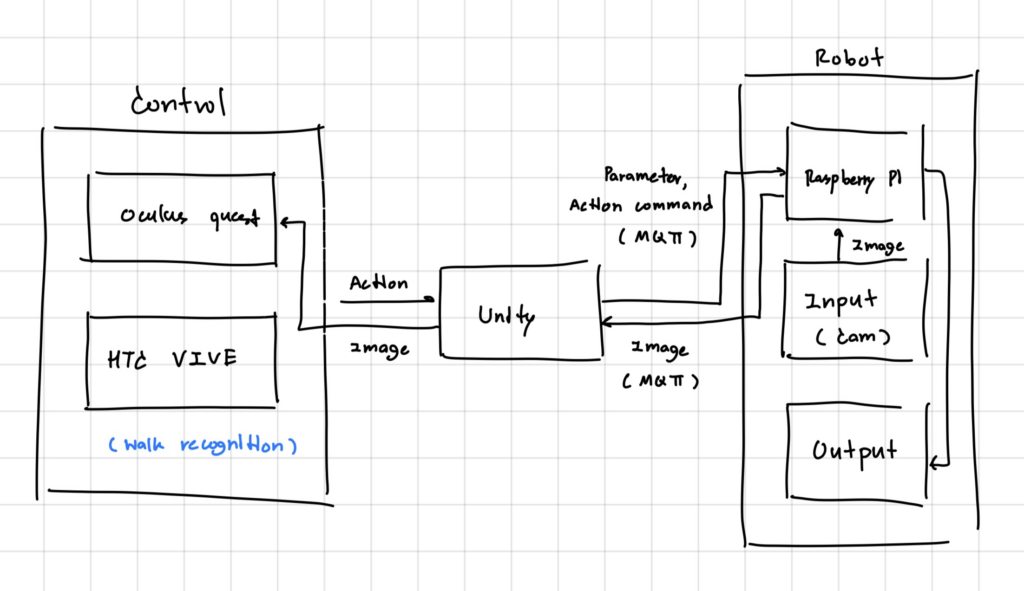
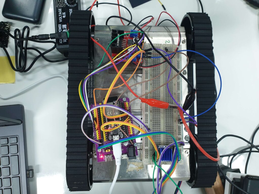
Design of mechanical part & hardware block diagram
In robot mechanical part, which control by Raspberry Pi it consist of movement part using two 12V DC motor, and L298N for controlling the direction and rpm (round per minute). The camera control assemble with two servo motor for controll pitch and yaw rotation movement.
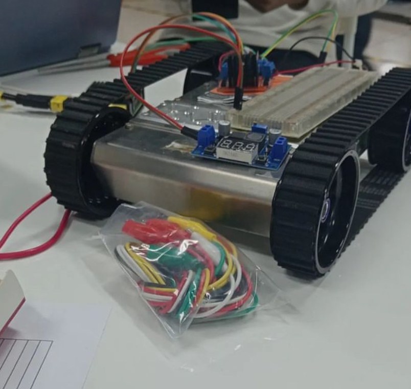
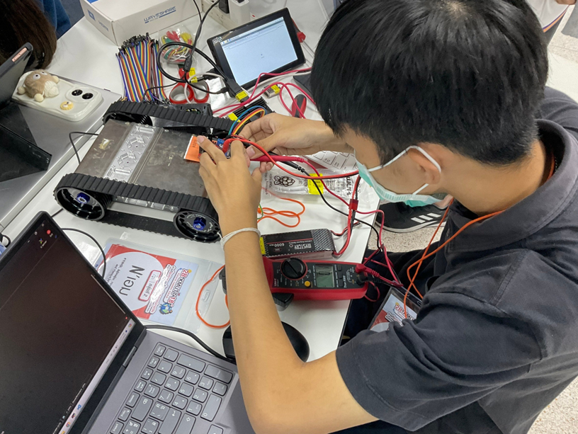
Hardware assembling
27/3/2024
Familiarize to Raspberry Pi (RPi)
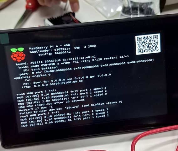
Raspberry Pi is a small computer, which consist of 3 main coponents, Raspberry Pi (processor), display monitor (output), keyboard and mouse (input). Because Raspberry Pi is the small computer, the using process is similar to normal use of computor (need to shutdown the board before power cut off). One of efficiency way to programming and control Raspberry Pi is to control via remote desktop from PC, or laptop using of Mobaxterm, it will display the terminal of Raspberry Pi, file manager, and a simple of performance information.
Raspberry Pi programming
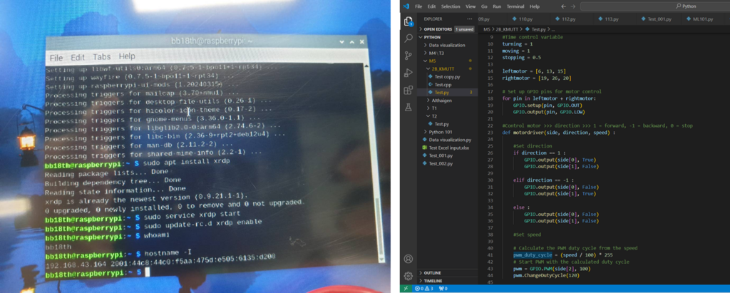
The programming language of Raspberry Pi is Python. It use Python language with RPi.GPIO library for setting the stat and action of pin. Using of remote desktop, can upload file from outside, to the board directly, which support of coding from outside source and uplode to the board easily.
Define error of hardware and software
In testing of a script in the Raspberry Pi for control motor driver, it have some problem about drive motor voltage lacking, which causing from pwm pin from the board. This problem was define by measuring the voltage drop across each point using of multimeter. The conclusion of this problem is the error syntax of pwm script in while loop make the sending of pwm from board to driver stuck and not supplying to the motor. This problem was solve by keep the erorr part inside the loop out and change the command used more correctly.
28/3/2024
Hardware update
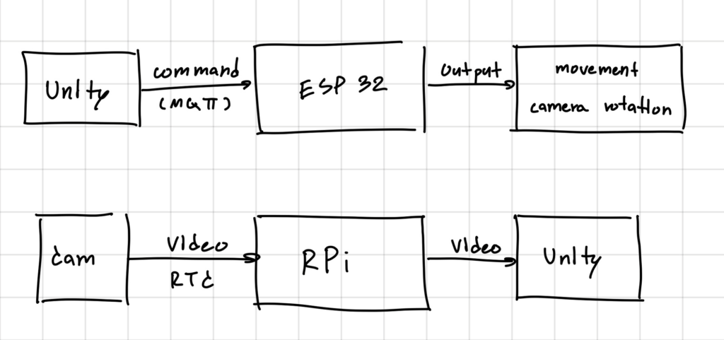
The hardware design was change to seperate into two parts using of ESP32 and Raspberry Pi, which play on different role as input and output processing. The Raspberry Pi was selected to be a input part, which connect with webcam and send the video, as the input using of RTC system to the Unity which will display to user, while ESP32 receive the command from Unity to control robot movement and camera rotation for the wide visibility area.
Robot movement control (hardware)
The hardware of robot movement was control by L298N motor driver, and used 12V. battery as the power supply of motor. The direction of motor was control by two pin of ESP32 by changing of digital state (0, 1) to change elecrticity flow, lead to the direction of dc motor (clockwise and counterclockwise), while the speed of motor or RPM (round per minute) was control using PWM to change the average supply voltage the motor get.
Output software
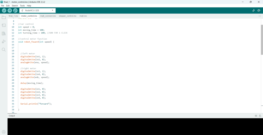
The software of robot was design to control in serial monitor, which will update to receive the command from Unity in future. The output script, which using c++ language for control ESP32, was split into 3 parts (sub routine), consist of main control for receive the input from user in serial monitor and call the corresponding function. Motor control part, focus on the setting direction and speed of motor, and servo control part, for control the servo angle in camera rotating.
29/3/2024
Study of MQTT
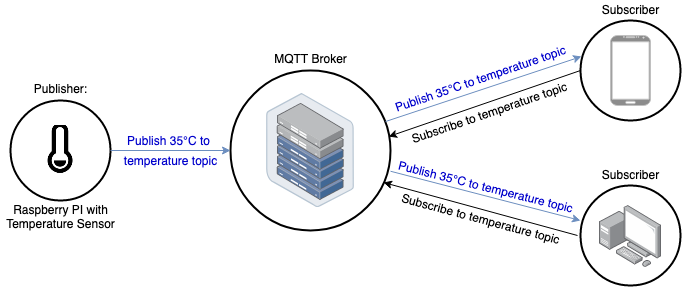
MQTT is protocol for sending and receive information (text/message) using internet, consist of three players, publisher, MQTT broker, and subbscriber, which role on sending message to broker, intermediary for receiving/sending message from publusher and subscriber, and receive the message from broker. In the process of sending and receiving message, publisher and subscriber need to have same “topic” (tag or key of the message) for send and receive message to the targeted client, which manipulating by MQTT broker. There are three QoS (quality of service) of MQTT type. “0”, treats all data equally without guarantees for delivery time or order. “1”, provides guaranteed levels of service by reserving resources for each data flow. “3”, classifies and prioritizes traffic based on predefined rules without reserving resources for each flow.
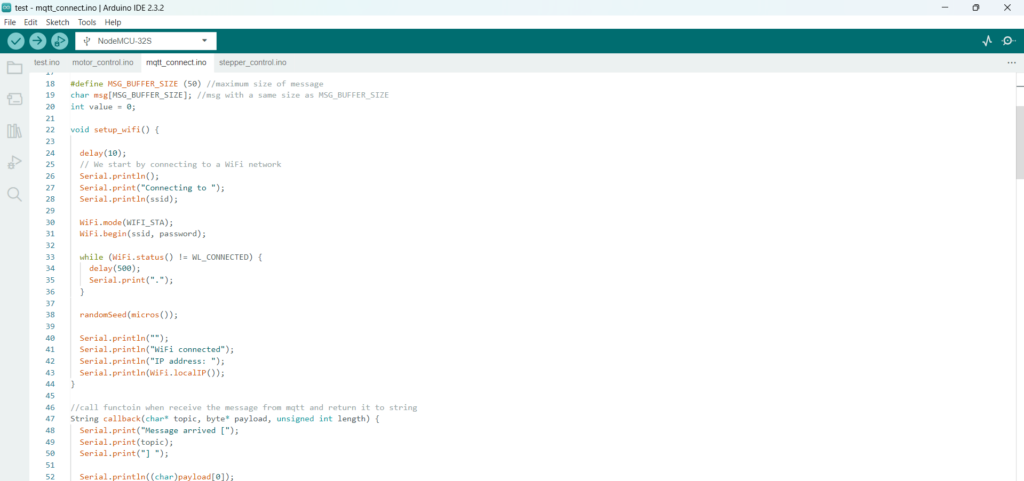
MQTT subscribe and publish for ESP32
Camera connecting design
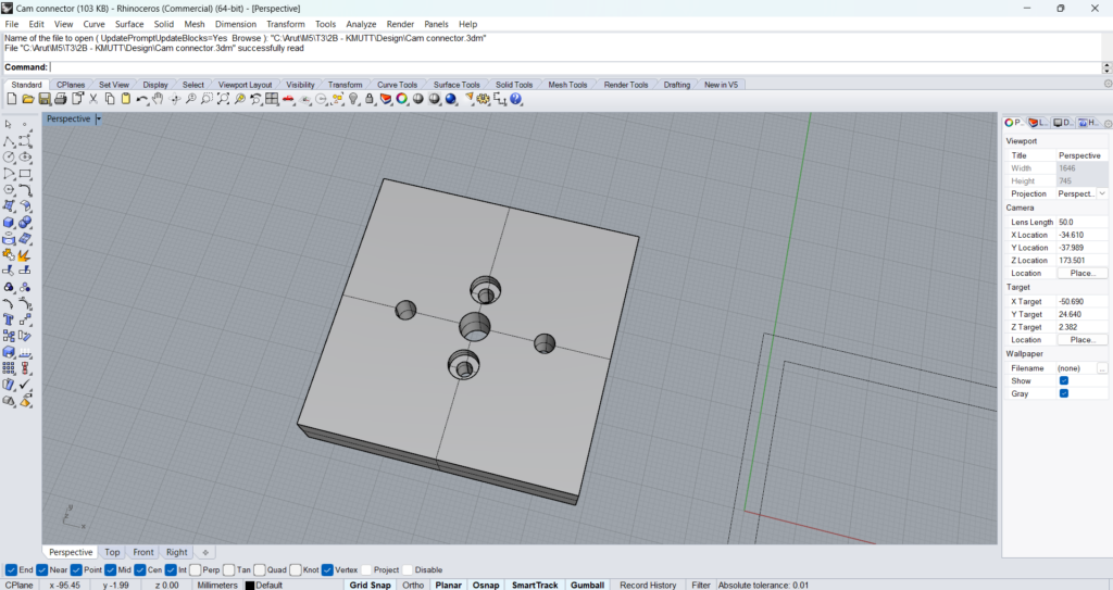
Camera connecting is the part between camera base and the motor for rotating the camera rotation. The camera connecting was design by Rhinoceroos program, it assemble to the camera and the flange coupler (stepper motor coupler) using four nuts. Two nuts using for connect with stepper was design to posotioning inside space between the camera connector and camera, to avoid the assembling problem from height of nuts, while two nuts for cinnect the camera and camera connector was design with simple method.
1/4/2024 – 2/4/2024
MQTT for controlling a robot movement
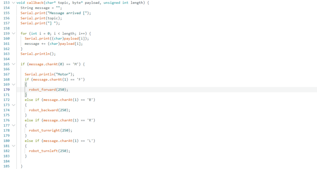
Using MQTT to control action of robot, was control in function callback for calling when the message is send to subscriber (ESP32). It was design to create string from a character in payload (message) and then checking for the first character. If the first character is “M” for motor, it will checking for the second position of string for the action, “F”, “B”, “L”, “R” (forward, backward, left, right).
MQTT for controlling camera rotation and stepper control
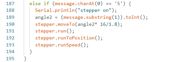
Camera rotation was control by stepper motor with driver (TMC2208). ESP32 setting the driver for the micro step for driving, step a motor move, and direction of stepper motor. MQTT for control the rotation of angle was processing when the first character of message reveied is “S” for stepper motor, it receive the angle by getting the string of message after the first character (“S”), turn it to integer value using toInt() function. The script for stepper motor was control using AccelStepper for setting the velocity, acceleration, and step the motor move.
3/4/2024 – 4/4/2024
Structure assembling
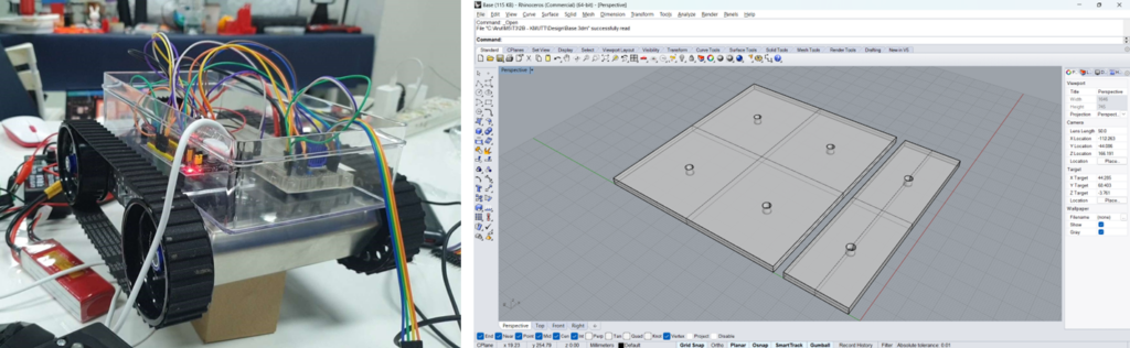
The structure of robot was design to have a box for packing the circuit and hardware inside more safety, while designing the robot, ensure that the base’s height is set at the same level.
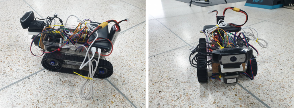
Final: The camera part, which consist of stepper motor and camera was attach to infront of the box while have 12V. battery and powerbank have attach from back.
Debug of MQTT and controlling system
The MQTT in the previous script have a problem about jump put of loop which make the process of receiving the message not continuously. With the many of message from publisher, it make the processing of robot not working well, which is the cause of delay in controlling system. This problem was solve by change the processing design to send message only when the action was change (example from waiting >> walking = 1 message, from walking >> waiting >> turn right = 2 message), this solve overflow of message receive make the robot processing without delay (0 sec. < delay time < 0.5 sec.), which improve efficiency and accuracy when controlling usign VR.
Final product